Heat Pumps and Energy Efficiency Influences – Making the right choice

Author

Nicky Cowan
Star Renewable Energy Manager
The UK's largest independent industrial refrigeration engineering company.
Nicky Cowan
Star Renewable Energy Manager
What to look for when purchasing energy efficient heat pumps for district heating & industrial processes.
Energy efficient heat pumps are proving to be a clean, affordable and efficient way of heating homes and commercial buildings through the utilisation of renewable sources. Hailed as the “only scalable renewable heating technology capable of becoming zero carbon by 2050” by renown industry experts at a high profile conference event in Warwick in October 2016, heat pumps are crucial in meeting the country’s current evasive carbon emissions targets and getting the UK back on track to achieve its COP21 targets.
With the CO2 intensity of the grid in continuous decline, the goal of a fuel poverty and carbon free heating future is closer than ever.
The difficulty of reducing emissions from other sectors, such as transport, means that heating may have to almost fully decarbonise if the UK is to hit its long-term goal of an 80% reduction in emissions by 2050, which means that by 2035, all new investment in heat will have to be zero-carbon.
If you are considering a heat pump for a new construction project, existing residential or industrial facilities; first you need to understand how a large scale heat pump works in order to benefit from both financial and environmental gains.
Read on to find out what criteria to use when purchasing industrial heat pump technology, what are the effects of any potential trade offs, and how to choose the right heatpump technology for your project.
Financial or Carbon Savings?
Why choose when you can have both. Heatpumps offer economic as well as environmental benefits.
In terms of £/kWs, the bigger the heatpump installation, the better: a 13MW heatpump costs in the region of £350 to £400/kW and will payback in a three (1) year period while a heatpump between 500kW and 1MW will be in the range of £500 to £700/kW with a ROI of 4 years.
When it comes to meeting carbon targets, heat pumps are a future-proof solution. As their only input is electricity, their carbon footprint is therefore tied to the electricity grids carbon content. As renewable electricity continues to be added to the grid (Hydro, On/offshore wind etc), the carbon intensity of the grid declines and consequently, heatpumps decarbonise- potentially becoming zero carbon.
Taking grid intensity figures in the UK – currently at 398 (3)gCO2/kWH – the carbon content of heat produced by a heat pump with a COP of 3 is 45% lower than gas (85% efficient boiler);
(398gCO2 /kWh) / (3 (COP)) = 132.6gCO2/kWh
(208gCO2/kWh) / (0.85 efficiency) =244.7gCO2/kWh
When using Scotland’s grid intensity figures at 196gCO2/kWH, CO2 savings increase above 73%.
(196gCO2 / kWh) / 3 (COP)= 65.3gCO2 / kWh
(208gCO2 / kWh) / (0.85 efficiency) = 244.7gCO2 / kWh
Note that the above figures from SAP are still under consultation and the final version will be released soon. This leaves a bit of a problem where consultants are still using values released by the government in 2012 when analysis by BRE showed that electricity generated in UK resulted in 519 grams of carbon dioxide (CO2) produced per kilowatt hour (kWH) of energy generated. Should we be comparing technology based on such an out of date number?
Below is a simplified model of how the CO2 content of technology will change over the following years. We can see that we are already at the point where heat pumps are better that CHP in terms of CO2 and as the grid carbon content continues to decline over the next 20 years. So, why install something over a heat pump that is only going to increase your carbon emissions?
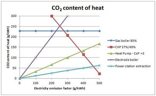
CO2 Content of Heat
Still Sceptical? Let’s look at a real case study
Have you heard about Star’s 13MW Heat pump in Norway which extracts warmth from ice cold water to provide heat and hot water to buildings, hospitals, and industry in Drammen, a city of 63,000 people? The heat pump takes water out of a local fjord at 8oC and returns it at 4oC (the source side). On the hot side (the bit doing District heating) it takes water in at 60oC and boost it up to 90oC through 3-off two stage compression heat pump systems. Star achieved a seasonal COP of 3 for this site by using various tricks to optimise heat recovery, including waste heat from oil coolers, waste heat from electric motors and staging the heating process. Typically you might see three heat pumps in parallel so each one individually is taking heat up from 60oC to 90oC. Instead, Star steps the heat up so one heat pump takes it from 60oC -70oC the next 70oC -80oC and the last 80oC-90oC (we also step the evaporation process), which allows the heat pump to achieve the best COP possible for each application.
The installation has delivered 350GWh of clean heat to date with savings totalling over €10m and carbon savings equivalent to driving over 10,000 times around the globe.
Ok, so that’s great but it’s in Norway what if we’ve done this in the UK?
A 13MW heat pump with a COP of 3 using RHI will make a payback in 4 years for a £5,000,000 investment. These types of projects are 100% viable in the UK. Just look out of the window, there is probably a river, lake, canal, loch, firth, sea, ocean or ground water not too far away, if not, it’s probably raining so there is plenty of water everywhere in the UK.
How does a Heat Pump work?
A water source heat pump takes water directly from any natural or artificial water stream, including aquifers, rivers, lakes, the sea and even London’s tube underground water could be utilised. Using compressors and heat exchangers, the heat pump takes the energy from the water and boosts it up through a refrigeration cycle, dumping the heat into the district water circuit. In the same way, industrial scale air source heat pumps take the warmth directly from the air and raise it to high temperatures for use in a wide range of applications. Different heat pumps work at different temperatures, but it is possible to heat water up to 90oC before being transferred to the heating system to be used for radiators and hot water.
Heat pumps can be built in a range of sizes, tailored to the specific’s projects needs. So, what constitutes as a large scale heat pump? Many people presume that a heat pump between 50kW and 100kW which can heat up to 60 degree C is as large scale as it can go. However, this is not the case. In fact, you can have as many kW or MW as required, as long as you have enough space for the units and water/air capacity.
Star are designing heat pumps big enough to provide heating and hot water to some of the largest town’s district heating schemes in the UK such as E.ON’s Cranbrook scheme, a network serving 3,500 new homes as well as 1.4 million square feet of industrial space, to the east of Exeter.
There are five main components in a water source heat pump:
Understanding Refrigeration Cycles
This is the confusing part, but it is essential you have a basic understanding so that you can separate the fact from fiction when liaising with suppliers and make and educated judgement.
A pressure enthalpy diagram can demonstrate how a refrigeration cycle works, and how it is possible to make it more efficient. It tells us how much work we need to do to get the best out of the heat pump.
In the following graphs there are four straight lines:

Pressure Enthalpy Diagram: The example above is set up for evaporating at 0 degrees C and condensing at 80 degrees C.
Look what happens when we increase the source temperature and decrease the district heating side temperature.
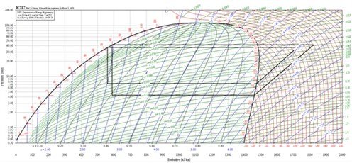
Pressure Enthalpy Diagram: Increased coefficient of performance (COP) by increasing source temperature and decreasing district heating temperature.
You can see that the compressor line (line1) is shorter, the evaporation point (line 4) has increased and the condensing line (line 2) has dropped down a bit. You can also see that the rectangle has jumped out slightly, on the left hand side. So, what’s this telling us? It’s saying that the compressor is doing less work to get more out of the heat pump. This translates as a better coefficient of performance (COP) – the number that tells you how efficient the heat pump is and in turn how affordable and environmentally friendly it is.
There’s another way to further increase the efficiency of the heat pump – by adding extra heat exchangers such as subcoolers and desuperheaters. Although not necessary to complete a refrigeration circuit, these elements can take some of the work from the compressor and create extra capacity for the heat pump.

Pressure Enthalpy Diagram: Increased coefficient of performance (COP) by adding extra heat exchangers.
*Not modelled in the diagram above :
-The desuperheater will also reduce the condensing temperature.
-Recovering the heat from oil coolers will also increase efficiency.
Sourcing Natural Energy
Depending on your surroundings, your natural energy source will differ. However, the same principles apply.
If there is a suitable water source near you and want a water source heat pump to provide low cost, low carbon heating and hot water –it could be a river, an ocean or you can even use waste heat from industry – be aware that when taking water from a natural source, you will need to contact the Environmental Protection Agency or SEPA. You may have to pay for a yearly abstraction license, and they will advise how much water can safely be removed from the river before putting it back.
Don’t forget that the starting temperature of the water has and effect on COP. The higher the source water temperature, the less the compressor has to work so if mineshafts are part of your local landscape, make sure you use them to improve the COP of the heat pump.
Rivers tend to be warmer in the summer and cooler in the winter so you may not have much control over the source water temperature – but you do have control over the district heating side. Remember, reducing the condensing temperature decreases the compressor work and increases the system’s efficiency
These considerations should play heavily into your feasibility studies.
For Reference: To put things into context, the interactive heat map released in 2015 by the Department of Energy and Climate Change, now known as BEIS, indicates the enormous potential of water source heat pumps in the UK. In England alone, more than 6 GW of renewable heat can be extracted from rivers and canals. With the UK’s long coastal line England, Wales, Scotland and Northern Ireland, the potential to extract further heat from the surrounding sea is huge.
From the 6GW available in rivers water source heat pumps can deliver 9GW of heat – the electricity used in the heatpump is also released in form of heat-.
If 9 GW of the overall 90GW heat capacity currently required for domestic and commercial sector in England can be generated using heat pumps instead of using gas boilers, 3.9 million tonnes of CO2 could be saved in 2017.
9 GW would provide affordable heat for an estimate 1.8 million homes across England – and that is only from our rivers.
By 2035, as the national grid becomes less carbon intensive, carbon savings will be twice as high.
Parallel and Complex Circuits
A parallel circuit is simple to install, but not the most efficient way of doing things. When planning to invest in a heat pump, ask if a complex circuit is possible to improve COP. Rather than having both circuits heating water from 60oC to 80oC, Star recommends taking the hot water through the condensers in series. The first one will take the water from 60oC to 70 degree C and then the next one 70 degree C to 80 degree C. This obviously results in less work for the compressor which can have a vast impact on COP.
Reading the TRUE heat pump COP
We’ve mentioned COP a lot, and if you’ve had a quote for a heat pump in the past then you would have received a COP value. However, was it as detailed as it needs to be? Was it just the shaft COP, were inverter losses taken into consideration? Source pump power?. You need to be aware of what exactly you’re getting from a supplier – it can make the difference between project success and project failure.
Take a look at our example COP calculation:
| Hot side flow/return Temp (Deg C) | 55/75 |
| Source Side Temp (Deg C) | 8/5 |
| Number of Units | 1 |
| Heat Pump Capacity (kW) | 1049.5 |
| Power – Shaft (kW) | 332.4 |
| COP | 3.16 |
| Motor Losses – Say 3% (kW) | 9.972 |
| Inverter Losses Say 3% (kW) | 9.67284 |
| New COP | 2.98 |
| Source Pump Power (kW) | 20 |
| Final COP | 2.82 |
The COP of 3.16 is the SHAFT COP. No losses have been taken into consideration for this 1MW system.
However if we are generous and say the motor and inverter are both 97% efficient we are now talking about a COP under 3!
OFGEM require you to include the source pump power as part of the RHI calculations – basically anything that is required to make a heat pump work needs to be taken into consideration. So picking just a random number of 20kW’s we now end up with a COP of 2.82.
The future of renewable energy
Heating consumes over 50% of our energy –more than electricity and transport combined- and costs the UK £16 billion a year in dirty fossil fuels imports. On the other hand, The World Health Organisation estimates air pollution annually costs the UK £62bn pounds and causes around 40,000 deaths a year, so finding complex ways of burning gas or importing biomass are unlikely options.
Imaging if half of the UK’s and indeed Europe’s greenhouse emissions could be cut down to zero. With the increase in green electricity production and the continuos decarbonisation of the grid, heat pumps offer the potential to become a zero carbon technology. If you’d like to find out more about heat pumps and if they could work for your project, get in touch.
References
This article has been certified for Continuing Professional Development (CPD) by CIBSE and The CPD Certification Service. To get your CPD Certificate please email your request to CPDCertificate@star-ref.co.uk